For the circuit shown in the figure below, assume that D₁, D₂ and D₃ are ideal. v(t) = π sin (100πt) V
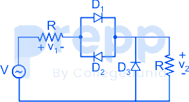
The DC components of voltages v₁ and v₂, respectively are
- A0 V and 1 V
- B-0.5 V and 0.5 V
- C1 V and 0.5 V
- D1 V and 1 V
Solution & Step-by-step Explanation
Concept:
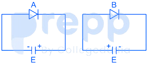
Forward Bias: When the p-type side of the diode is connected to a higher potential than the n-type side, the diode is said to be forward-biased i.e., ON
Reverse Bias: When the case is opposite and n-type side is kept at a higher potential than the p-type side i.e., OFF
Analysis:
At positive pulse, D₁ is ON, D₂is OFF and D₃ is OFF.
and in the negative half cycle, D₁ is OFF and D₂ and D₃ are ON. The circuit acts as a half-wave rectifier.
The output of the half-wave rectifier circuit will be:
For positive pulse:
For negative pulse, D₁ is OFF, D₂ is ON and D₃ is ON. Hence resister across D₃ gets short-circuited. total voltage appears across the first resistor.
Forward Bias: When the p-type side of the diode is connected to a higher potential than the n-type side, the diode is said to be forward-biased i.e., ON
Reverse Bias: When the case is opposite and n-type side is kept at a higher potential than the p-type side i.e., OFF
Analysis:
At positive pulse, D₁ is ON, D₂is OFF and D₃ is OFF.
and in the negative half cycle, D₁ is OFF and D₂ and D₃ are ON. The circuit acts as a half-wave rectifier.
The output of the half-wave rectifier circuit will be:
For positive pulse:
For negative pulse, D₁ is OFF, D₂ is ON and D₃ is ON. Hence resister across D₃ gets short-circuited. total voltage appears across the first resistor.