100% Free
GATE EC 2016 Question Paper (30-Jan-2016) (Shift 1)
Medium 65 Questions 180 min 100 marks
⚡ Live Test Mode Available
Take this as a timed mock test
180 min · 100 marks · Full test mode with leaderboard
Advertisement
Previous Year Questions
65medium5
Questions
0
Attempted
0
Correct
0
Wrong
0/5 attempted
Question No: 46Difficulty: mediumMarks: 2short_answer
Consider a silicon p-n junction with a uniform acceptor doping concentration of 10¹⁷ cm on the p side and a uniform donor doping concentration of 10¹⁶ cm−3 on the n-side. No external voltage is applied to the diode. Given: kT/ = 26 mV, nᵢ =1.5 ×10¹⁰ cm⁻³, ε = 12ε₀, ε₀ = 8.85 × 10⁻¹⁴ F/m, and q = 1.6 ×10⁻¹⁹ C. The charge per unit junction area (nC cm⁻²) in the depletion region on the p-side is ___________.
Question No: 47Difficulty: mediumMarks: 2short_answer
Consider an n-channel metal-oxide-semiconductor field-effect transistor (MOSFET) with a gate-to-source voltage of 1.8 V. Assume that , μₙCₒₓ = 70 × 10⁻⁶ AV⁻², the threshold voltage is 0.3 V, and the channel length modulation parameter is 0.09 V⁻¹. In the saturation region, the drain conductance (in micro seimens) is ________.
Question No: 48Difficulty: mediumMarks: 2short_answer
The figure below shows the doping distribution in a p-type semiconductor in log scale.
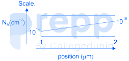
The magnitude of the electric field (in kV/cm) in the semiconductor due to non-uniform
doping is _________.
The magnitude of the electric field (in kV/cm) in the semiconductor due to non-uniform
doping is _________.
Question No: 49Difficulty: mediumMarks: 2mcq
Consider a silicon sample at T = 300 K, with a uniform donor density 𝑁 = 5 × 10¹⁶
cm⁻³, illuminated uniformly such that the optical generation rate is 𝐺 = 1.5 × 10²⁰cm⁻³𝑠⁻¹ throughout the sample. The incident radiation is turned off at 𝑡 = 0. Assume low-level injection to be valid and ignore surface effects. The carrier lifetimes are 𝜏 = 0.1 μs and 𝜏 = 0.5 μs.
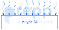
The hole concentration at 𝑡 = 0 and the hole concentration at 𝑡 = 0.3 μs, respectively, are
cm⁻³, illuminated uniformly such that the optical generation rate is 𝐺 = 1.5 × 10²⁰cm⁻³𝑠⁻¹ throughout the sample. The incident radiation is turned off at 𝑡 = 0. Assume low-level injection to be valid and ignore surface effects. The carrier lifetimes are 𝜏 = 0.1 μs and 𝜏 = 0.5 μs.
The hole concentration at 𝑡 = 0 and the hole concentration at 𝑡 = 0.3 μs, respectively, are
Question No: 50Difficulty: mediumMarks: 2short_answer
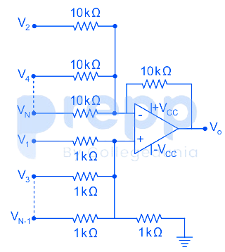
An ideal opamp has voltage sources V₁, V₃, V₅, …, V connected to the non-inverting input and V₂, V₄, V₆, …, V connected to the inverting input as shown in the figure below (+V = 15 volt, −V = −15 volt). The voltages V₁, V₂, V₃, V₄, V₅, V₆,… are 1, − 1/2, 1/3, −1/4, 1/5, −1/6, … volt, respectively. As N approaches infinity, the output voltage (in volt) is ___________
✓ Showing questions 46–50 of 65 — use the page buttons below to practice the rest
You May Also Like
📊 Track Your Progress
Know exactly where you stand
Save scores, track weak topics, compare with toppers — all free.
Advertisement