100% Free
GATE EE 2018 Question Paper (10-Feb-2018) (Shift 2)
Medium 65 Questions 180 min 100 marks
⚡ Live Test Mode Available
Take this as a timed mock test
180 min · 100 marks · Full test mode with leaderboard
Advertisement
Previous Year Questions
65medium5
Questions
0
Attempted
0
Correct
0
Wrong
0/5 attempted
Question No: 61Difficulty: mediumMarks: 2nat
A 3-phase 900 kVA, 3 kV/ kV (∆/Y), 50 Hz transformer has primary (high voltage side) resistance per phase of 0.3 Ω and secondary (low voltage side) resistance per phase of 0.02 Ω. Iron loss of the transformer is 10 kW. The full load % efficiency of the transformer operated at unity power factor is _______ (up to 2 decimal places).
Question No: 62Difficulty: mediumMarks: 1nat
A 200 V DC series motor, when operating from rated voltage while driving a certain load, draws 10 A current and runs at 1000 r.p.m. The total series resistance is 1 Ω. The magnetic circuit is assumed to be linear. At the same supply voltage, the load torque is increased by 44%. The speed of the motor in r.p.m. (rounded to the nearest integer) is ________
Question No: 63Difficulty: mediumMarks: 2nat
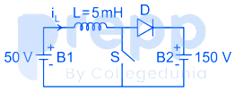
A dc to dc converter shown in the figure is charging a battery bank, B2 whose voltage is constant at 150 V. B1 is another battery bank whose voltage is constant at 50 V. The value of the inductor, L is 5 mH and the ideal switch, S is operated with a switching frequency of 5 kHz with a duty ratio of 0.4. Once the circuit has attained steady-state and assuming the diode D to be ideal, the power transferred from B1 to B2 (in Watt) is ___________ (up to 2 decimal places).
Question No: 64Difficulty: mediumMarks: 2nat
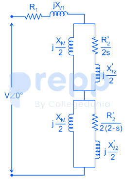
The equivalent circuit of a single-phase induction motor is shown in the figure, where the parameters are R₁= R’₂ = Xₗ₁= X’ₗ₂= 12 Ω, x = 240 Ω and s is the slip. At no-load, the motor speed can be approximated to be the synchronous speed. The no-load lagging power factor of the motor is___________ (up to 3 decimal places).
Question No: 65Difficulty: mediumMarks: 2nat
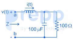
The voltage v(t) across the terminals a and b as shown in the figure, is a sinusoidal voltage having a frequency ω = 100 radian/s. When the inductor current i(t) is in phase with the voltage v(t), the magnitude of the impedance Z (in Ω) seen between the terminals a and b is ________ (up to 2 decimal places).
✓ Showing questions 61–65 of 65 — use the page buttons below to practice the rest
You May Also Like
📊 Track Your Progress
Know exactly where you stand
Save scores, track weak topics, compare with toppers — all free.
Advertisement