100% Free
GATE EE 2020 Question Paper (08-Feb-2020) (Shift 1)
Medium 65 Questions 180 min 100 marks
⚡ Live Test Mode Available
Take this as a timed mock test
180 min · 100 marks · Full test mode with leaderboard
Advertisement
Previous Year Questions
65medium5
Questions
0
Attempted
0
Correct
0
Wrong
0/5 attempted
Question No: 56Difficulty: mediumMarks: 2nat
A cylindrical rotor synchronous generator with constant real power output and constant terminal voltage is supplying 100 A current to a 0.9 lagging power factor load. An ideal reactor is now connected in parallel with the load, as a result of which the total lagging reactive power requirement of the load is twice the previous value while the real power remains unchanged. The armature current is now A (rounded off to 2 decimal places).
Question No: 57Difficulty: mediumMarks: 2nat
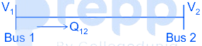
Bus 1 with voltage magnitude V₁ = 1.1 pu is sending reactive power Q₁₂ towards bus 2 with voltage magnitude V₂ = 1 pu through a lossless transmission line of reactance X. Keeping the voltage at bus 2 fixed at 1 pu, magnitude of voltage at bus 1 is changed, so that the reactive power Q₁₂ sent from bus 1 is increased by 20%. Real power flow through the line under both the conditions is zero. The new value of the voltage magnitude, V₁, in pu (rounded off to 2 decimal places), at bus 1 is ________.
Question No: 58Difficulty: mediumMarks: 2nat
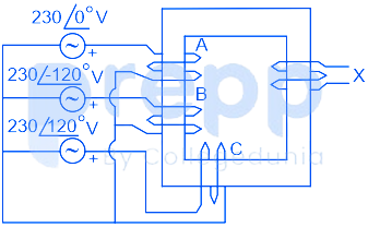
Windings 'A', 'B' and 'C' have 20 turns each and are wound on the same iron core as shown, along with winding 'X' which has 2 turns. The figure shows the sense (clockwise/anti-clockwise) of each of the windings only and does not reflect the exact number of turns. If windings 'A', 'B' and 'C' are supplied with balanced 3-phase voltages at 50 Hz and there is no core saturation, the no-load RMS voltage (in V, rounded off to 2 decimal places) across winding 'X' is
Question No: 59Difficulty: mediumMarks: 2nat
A cylindrical rotor synchronous generator has steady state synchronous reactance of 0.7 pu and sub transient reactance of 0.2 pu. It is operating at (1 + j0) pu terminal voltage with an internal emf of (1 + j0.7) pu. Following a three-phase solid short circuit fault at the terminal of the generator, the magnitude of the sub transient internal emf (rounded off to 2 decimal places) is______ pu.
Question No: 60Difficulty: mediumMarks: 2nat
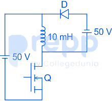
In the dc-dc converter circuit shown, switch Q is switched at a frequency of 10 kHz with a duty ratio of 0.6. All components of the circuit are ideal, and the initial current in the inductor is zero. Energy stored in the inductor in mJ (rounded off to 2 decimal places) at the end of 10 complete switching cycles is ________
✓ Showing questions 56–60 of 65 — use the page buttons below to practice the rest
You May Also Like
📊 Track Your Progress
Know exactly where you stand
Save scores, track weak topics, compare with toppers — all free.
Advertisement