100% Free
GATE EE 2023 Question Paper (05-Feb-2023) (Shift 1)
Medium 65 Questions 180 min 100 marks
⚡ Live Test Mode Available
Take this as a timed mock test
180 min · 100 marks · Full test mode with leaderboard
Advertisement
Previous Year Questions
65medium5
Questions
0
Attempted
0
Correct
0
Wrong
0/5 attempted
Question No: 56Difficulty: mediumMarks: 2nat
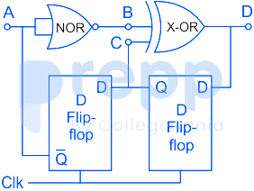
Neglecting the delays due to the logic gates in the circuit shown in figure, the decimal equivalent of the binary sequence [ABCD] of initial logic states, which will not change with clock, is ____________.
Question No: 57Difficulty: mediumMarks: 2nat
In a given 8-bit general purpose micro-controller there are following flags.
C-Carry, A-Auxiliary Carry, O-Overflow flag, P-Parity (0 for even, 1 for odd)
R0 and R1 are the two general purpose registers of the micro-controller.
After execution of the following instructions, the decimal equivalent of the binary sequence of the flag pattern [CAOP] will be __________.
MOV R0, +0x60
MOV R1, +0x46
ADD R0, R1
C-Carry, A-Auxiliary Carry, O-Overflow flag, P-Parity (0 for even, 1 for odd)
R0 and R1 are the two general purpose registers of the micro-controller.
After execution of the following instructions, the decimal equivalent of the binary sequence of the flag pattern [CAOP] will be __________.
MOV R0, +0x60
MOV R1, +0x46
ADD R0, R1
Question No: 58Difficulty: mediumMarks: 2nat
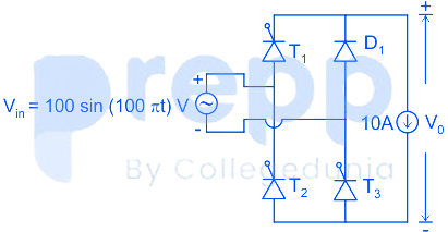
The single phase rectifier consisting of three thyristors T₁, T₂, T₃ and a diode D₁ feed power to a 10 A constant current load. T₁ and T₃ are fired at α = 60° and T₂ is fired at α = 240°. The reference for α is the positive zero crossing of Vᵢₙ. The average voltage V across the load in volts is _____ (Round off to 2 decimal places).
Question No: 59Difficulty: mediumMarks: 2nat
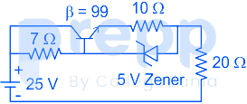
The Zener diode in circuit has a breakdown voltage of 5 V. The current gain β of the transistor in the active region in 99. Ignore base-emitter voltage drop V. The current through the 20 Ω resistance in milliamperes is ________(Round off to 2 decimal places).
Question No: 60Difficulty: mediumMarks: 2nat
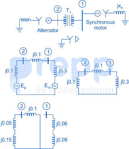
The two-bus power system shown in figure (i) has one alternator supplying a synchronous motor load through a Y-Δ transformer. The positive, negative and zero-sequence diagrams of the system are shown in figures (ii), (iii) and (iv), respectively. All reactances in the sequence diagrams are in p.u. For a bolted line-to-line fault (fault impedance = zero) between phases ‘b’ and ‘c’ at bus 1, neglecting all pre-fault currents, the magnitude of the fault current (from phase ‘b’ to ‘c’) in p.u. is _____________ (Round off to 2 decimal places).
✓ Showing questions 56–60 of 65 — use the page buttons below to practice the rest
You May Also Like
📊 Track Your Progress
Know exactly where you stand
Save scores, track weak topics, compare with toppers — all free.
Advertisement