100% Free
PYQs Based test 12: Power Systems
Medium 20 Questions 180 min 32 marks
⚡ Live Test Mode Available
Take this as a timed mock test
180 min · 32 marks · Full test mode with leaderboard
Advertisement
Previous Year Questions
20medium5
Questions
0
Attempted
0
Correct
0
Wrong
0/5 attempted
Question No: 11Difficulty: mediumMarks: 2nat
The overcurrent relays for the line protection and loads connected at the buses are shown in the figure.
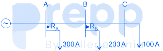
The relays are IDMT in nature having the characteristic
The maximum and minimum fault currents at bus B are 2000 A and 500 A respectively. Assuming the time multiplier setting and plug setting for relay RB to be 0.1 and 5A respectively, the operating time of RB (in seconds) is_______
The relays are IDMT in nature having the characteristic
The maximum and minimum fault currents at bus B are 2000 A and 500 A respectively. Assuming the time multiplier setting and plug setting for relay RB to be 0.1 and 5A respectively, the operating time of RB (in seconds) is_______
Question No: 12Difficulty: mediumMarks: 2mcq
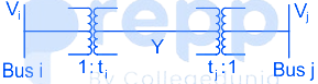
Two buses, i and j, are connected with a transmission line of admittance Y, at the two ends of which there are ideal transformers with turns ratios as shown. Bus admittance matrix for the system is:
Question No: 13Difficulty: mediumMarks: 2nat
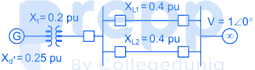
In the single machine infinite bus system shown below, the generator is delivering the real power of 0.8 pu at 0.8 power factor lagging to the infinite bus. The power angle of the generator in degrees (round off to one decimal place) is _________.
Question No: 14Difficulty: mediumMarks: 2nat
A 30 kV, 50 Hz, 50 MVA generator has the positive, negative, and zero sequence reactance’s of 0.25 pu, 0.15 pu, and 0.05 pu, respectively. The neutral of the generator is grounded with a reactance so that the fault current for a bolted LG fault and that of a bolted three-phase fault at the generator terminal are equal. The value of grounding reactance in ohms (round off to one decimal
Question No: 15Difficulty: mediumMarks: 1mcq
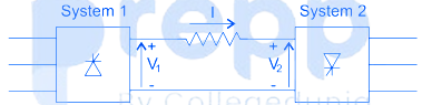
Consider a HVDC link which uses thyristor based line commutated converters as shown in the figure. For a power flow of 750 MW from system 1 to system 2, the voltages at the two ends, and the current, are given by: V₁ = 500 kV, V₂ = 485 kV and I = 1.5 kA. If the direction of power flow is to be reversed (that is, from system 2 to system 1) without changing the electrical connections, then which one of the following combinations is feasible?
✓ Showing questions 11–15 of 20 — use the page buttons below to practice the rest
You May Also Like
📊 Track Your Progress
Know exactly where you stand
Save scores, track weak topics, compare with toppers — all free.
Advertisement