100% Free
PYQs Based test 3: Electric Circuits
Medium 20 Questions 180 min 32 marks
⚡ Live Test Mode Available
Take this as a timed mock test
180 min · 32 marks · Full test mode with leaderboard
Advertisement
Previous Year Questions
20medium5
Questions
0
Attempted
0
Correct
0
Wrong
0/5 attempted
Question No: 1Difficulty: mediumMarks: 1mcq
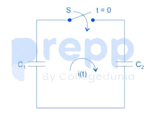
In the following figure, C₁ and C₂ are ideal capacitors. C₁ has been charged to 12 V before the ideal switch S is closed at t = 0. The current i(t) for all t is
Question No: 2Difficulty: mediumMarks: 2mcq
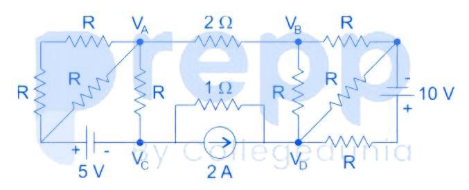
If V – V = 6 V then V – V is
Question No: 3Difficulty: mediumMarks: 1mcq
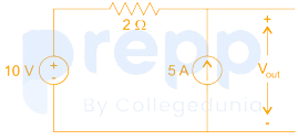
In the circuit shown below, the voltage and current sources are ideal. The voltage V ₒᵤₜ across the current source, in volts, is
Question No: 4Difficulty: mediumMarks: 1mcq
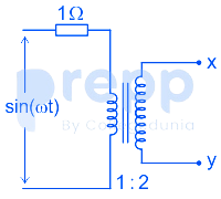
Assuming an ideal transformer, The Thevenin’s equivalent voltage and impedance as seen from the terminals x and y for the circuit in the figure are
Question No: 5Difficulty: mediumMarks: 2nat
The total power dissipated in the circuit, show in the figure, is 1kW.
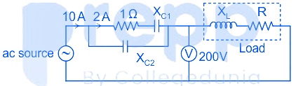
The voltmeter, across the load, reads 200 V. The value of X in ohms is __________.
The voltmeter, across the load, reads 200 V. The value of X in ohms is __________.
✓ Showing questions 1–5 of 20 — use the page buttons below to practice the rest
You May Also Like
📊 Track Your Progress
Know exactly where you stand
Save scores, track weak topics, compare with toppers — all free.
Advertisement