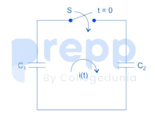
In the following figure, C₁ and C₂ are ideal capacitors. C₁ has been charged to 12 V before the ideal switch S is closed at t = 0. The current i(t) for all t is
- AZero
- BA step function
- CAn exponentially decaying function
- DAn impulse function
Solution & Step-by-step Explanation
The S – domain equivalent circuit is

V (0) = 12 V
I(S) = 12 C
Taking Inverse Laplace transform for the current in the time domain.
i(t) = 12 C δ(t)
The above equation shows that it's an impulse.
V (0) = 12 V
I(S) = 12 C
Taking Inverse Laplace transform for the current in the time domain.
i(t) = 12 C δ(t)
The above equation shows that it's an impulse.