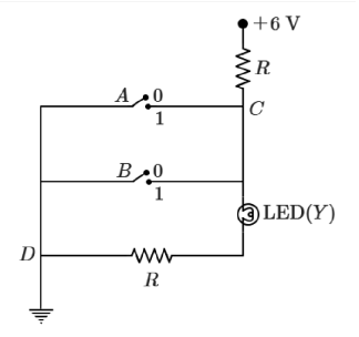
The circuit diagram shown here corresponds to the logic gate:
- ANOR
- BAND
- COR
- DNAND
Solution & Step-by-step Explanation
In the 2019 NEET paper, the diagram featured two inputs and connected via resistors to a transistor circuit that implements the operation. This corresponds to a NAND gate.