HomeTestsSearchRankProfile

Logic Gates Questions

Practice 28 Logic Gates questions with detailed answers and explanations. Free MCQs, PYQs, and mock test questions for NEET, JEE, GATE, SSC and more.

📚
28
Total Questions
🟢
10
Easy
🟡
16
Medium
🔴
2
Hard
Practice by Exam:Physics(27)PHYSICS(1)

About Logic Gates — practice questions, PYQs & concepts

Logic Gates is a frequently-tested topic on Physics, PHYSICS. ExamTest.live currently lists 28 Logic Gates questions spanning previous-year papers from 2026 to 2026, each with worked solutions and a step-by-step explanation. Use the filters on this page to focus on a specific exam, difficulty level or year — every answer key is free, no sign-up required.

Logic Gates weight in competitive exams

Across our Logic Gates question bank, the largest sources are Physics (27) and PHYSICS (1). Click any exam chip above to drill down to that exam-specific question set.

How to use this page

  • Start easy: 10 easy Logic Gates questions are available — build fluency before moving up.
  • Target weak years: Use the year filter to focus on the most recent 2026 paper or older PYQs you have not attempted.
  • Time yourself: Every question shows the average solve time so you can benchmark your speed against other students.
  • Read every explanation: Even on questions you got right — the explanation often surfaces a faster approach you can reuse.

All Logic Gates Questions(128 of 28)

Filter:
Q1mediummcqPhysicsNEET 20192026
0% accuracy
The correct Boolean operation represented by the circuit diagram drawn is:
image
Q2easymcqPhysicsNEET (UG) 20172026
0% accuracy
Two NOT gates are connected to the inputs of a NOR gate. The given electrical network is equivalent to:
image
Q3mediummcqPhysicsAIEEE 20122026
Truth table for system of four NAND gates as shown in figure (where are inputs to a NAND, its output splits to two NANDs, and their outputs go to a final NAND) is equivalent to:
image
image
Q4mediummcqPhysicsAIEEE2026
A logic gate circuit has two inputs and . Both are passed through NOT gates, then through a NAND gate, and finally through another NOT gate. This combination yields:
image
Q5mediummcqPhysicsAIEEE 20092026
The logic circuit shown below has the input waveforms ' ' and ' ' as shown. Pick out the correct output waveform.
image
Q6easymcqPhysicsAIEEE2026
A circuit has two inputs A and B and output C. The truth table shows C is 0 only when both A and B are 0, and C is 1 otherwise. This circuit represents:
Q7mediummcqPhysicsNEET (UG) 20242026
The output () of the given logic gate is similar to the output of an/a:
image
Q8mediummcqPhysicsNEET (UG) 20242026
A logic circuit provides the output as per the following truth table: image 
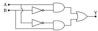
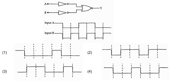
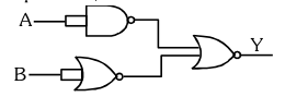
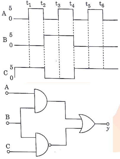
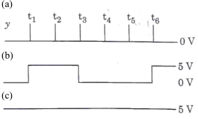
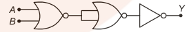
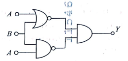
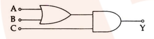
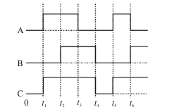
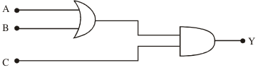
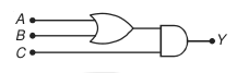
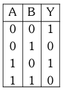
The expression for the output is:
Q9hardmcqPhysicsNEET 20232026
For the following logic circuit, the truth table is:
image
Q10hardmcqPhysicsNEET 20222026
The truth table for the given logic circuit is:
image

image
Q11mediummcqPhysicsNEET 20212026
For the given circuit, the input digital signals are applied at the terminals and . What would be the output at the terminal ?
image
Options:
image
image
Q12easymcqPhysicsNEET 2020 E12026
For the logic circuit shown (two NAND gates), the truth table is:
image
image
Q13easymcqPHYSICSNEET 20192026
The circuit diagram shown here corresponds to the logic gate:
image
Q14easymcqPhysicsNEET (UG) 20182026
In the combination of logic gates, where inputs and are fed into two NAND gates whose outputs are then fed into a third NAND gate, the output can be written as:
image
Q15easymcqPhysicsNEET 20172026
The given electrical network is equivalent to:
image
Q16mediummcqPhysicsPhysics
6% accuracy
The output () of the given logic implementation is similar to the output of an/a _________ gate.

image
Q17mediummcqPhysicsPhysics
0% accuracy
Symbolic representation of four logic gates are shown as:(i) OR gate AND gate NOT gate [NAND gate]Pick out which ones are for AND, NAND and NOT gates, respectively:
image
Q18mediummcqPhysicsPhysics
What is the output in the following circuit, when all the three inputs are first 0 and then 1?
image
Q19mediummcqPhysicsPhysics
To get output 1 for the following circuit, the correct choice for the input is:
image
Q20easymcqPhysicsPhysics
The output () of a NAND gate followed by a NOT gate is equivalent to:
image
Q21mediummcqPhysicsPhysics
The figure shows a logic circuit with two inputs and and the output . The voltage wave forms across and are as given. The logic circuit gate is:
image
Q22easymcqPhysicsPhysics
To get an output in the given circuit (AND gate with inputs and then OR gate with ), which of the following input will be correct:
image
Q23mediummcqPhysicsPhysics
To get an output from the circuit shown below, the input must be ():
image
Q24mediummcqPhysicsPhysics
The symbolic representations of four logic gates are given. The symbols for OR, NOT and NAND gates are respectively:
image
Q25mediummcqPhysicsPhysics
The circuit shown is equivalent to:
Q26mediummcqPhysicsPhysics
In the following circuit, the output for all possible inputs and is expressed by the truth table:ShutterstockExplore
Q27easymcqPhysicsPhysics
Assertion: The logic gate NOT can be built using diode.Reason: The output voltage and the input voltage of the diode have phase difference.
Q28easymcqPhysicsPhysics
Which of the following logic gates is an universal gate?

Frequently Asked Questions

How many Logic Gates questions are on ExamTest.live?
We have 28 Logic Gates questions spread across 1 pages, covering easy, medium, and hard difficulty levels with detailed explanations.
Are Logic Gates MCQs free?
Yes. All Logic Gates questions, answers, and explanations on ExamTest.live are completely free. No account or subscription required.
Which exams include Logic Gates questions?
Logic Gates questions are commonly asked in Physics, PHYSICS. You can filter by exam using the links above.
How do I practice Logic Gates questions effectively?
Start with easy questions to build confidence, then tackle medium and hard ones. Use the filter buttons to sort by difficulty. Reveal the answer only after attempting each question, and read the explanation thoroughly.