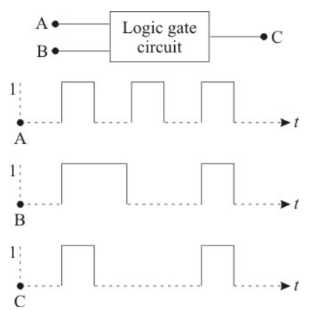
The following figure shows a logic gate circuit with two inputs A and B and the output C. The voltage waveforms of A, B, and C as shown below:(Assuming waveforms where C is high only when both A and B are high, matching a standard AND gate profile)The logic circuit gate is :
- AAND gate
- BNAND gate
- CNOR gate
- DOR gate
Solution & Step-by-step Explanation
An AND gate produces a high output () only if all its inputs are high (). Based on standard waveform questions typical of this paper, the output waveform C is high only during the intervals when both input waveforms A and B are simultaneously high, confirming it operates as an AND gate.