HomeTestsSearchRankProfile
mediumMCQPYQs Based Test - 02 : Electrical Circuits and MachinesInstrumentation Engineering
1 mark (−0.33)

A load resistor R is connected to a battery of voltage E with internal resistance Rᵢ through a resistance R as shown in the figure. For fixed values of R and Rᵢ, the value of R (≥ 0) for maximum power transfer to R is
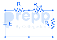
image

  1. A
    0
  2. B
    R - Rᵢ
  3. C
    R
  4. D
    R + Rᵢ

Solution & Step-by-step Explanation

Analysis:

Finding the voltage across load resistance using voltage division rule, we get:


Power loss in the R is given as:


We conclude that maximum power is transferred to R when RS = 0

image

Maximum power theorem states that for maximum power to be transferred to the load resistance RL, RL must equal the Thevenin Equivalent resistance, i.e.

RL = Rth

But here, we are asked to find the value of R, and not RL that will result in the maximum power to be transferred to load RL. So we cannot go by the standard procedure of equating RL with the Thevenin equivalent resistance.

Practice this question

Try it yourself before checking the explanation above.

A load resistor R is connected to a battery of voltage E with internal resistance Rᵢ through a resistance R as shown in the figure. For fixed values of R and Rᵢ, the value of R (≥ 0) for maximum power transfer to R is

image
A
0
B
R - Rᵢ
C
R
D
R + Rᵢ

Share This Question

Related Questions

mediumMCQ

A 2n × 2n matrix A=[a_ij] has its elements as a_ij = β & if (i+j) is odd, \\ -β & if (i+j) is even, where n is any integer greater than 2 and β is any non-zero real number. The rank of A is

mediumMCQ

The solution of the differential equation dy/dx = 9x/y represents

mediumMCQ

The working of the hand-held metal detector most widely used by security personnel for human frisking is based on the principle of

mediumMCQ

The primary coil of a linear variable differential transformer (LVDT) is supplied with AC voltage as shown in the figure. The secondary coils are connected in series opposition and the output is measured using a true RMS voltmeter. The displacement x of the core is indicated in mm on a linear scale. At the null position x = 0 , the voltmeter reads 0 V. If the voltmeter reads 0.2 V for a displacement of x = +2 mm, then for a displacement of x =-3 mm, the voltmeter reading, in V, is ![image](https://cdn.prepp.in/uploads/production/images/content/2025_11_17/image_7cdc73f01763403640224.png)

mediumMCQ

In the force transducer shown in Figure (a), four identical strain gauges S1, S2, S3, and S4 are mounted on a cantilever at equal distance from its base. S1 and S2 are mounted on the top surface and S3 and S4 are mounted on the bottom surface, as shown in the Figure (a). These strain gauges are to be connected to form a Wheatstone bridge consisting of four arms A, B, C, and D, as shown in the Figure (b). From the following options, the correct order to maximize the measurement sensitivity is ![image](https://cdn.prepp.in/uploads/production/images/content/2025_11_17/image_b4a3a5441763403707068.png)

mediumMCQ

Let a continuous-time signal be x(t) = e^j9t+e^j5t , where j = √(-1) and t is in seconds. The fundamental period of magnitude of x(t) , in seconds, is

Ready for a Full Test?

Practice with timed mock tests and track your performance across Instrumentation Engineering.

Discussion