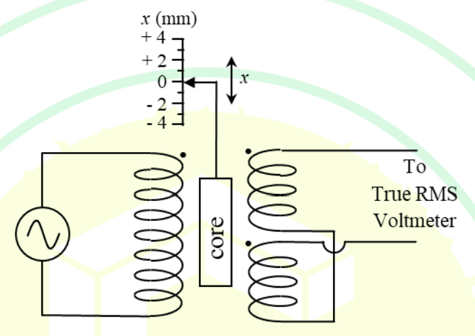
The primary coil of a linear variable differential transformer (LVDT) is supplied with AC voltage as shown in the figure. The secondary coils are connected in series opposition and the output is measured using a true RMS voltmeter. The displacement of the core is indicated in mm on a linear scale. At the null position , the voltmeter reads 0 V. If the voltmeter reads 0.2 V for a displacement of mm, then for a displacement of mm, the voltmeter reading, in V, is
- A-0.3
- B-0.1
- C0.3
- D0.5
Solution & Step-by-step Explanation
The problem involves a Linear Variable Differential Transformer (LVDT), which is a type of electromechanical transducer used for measuring linear displacement. The LVDT produces an AC output voltage that is proportional to the displacement of its core.
From the information given:
- At the null position (), the output voltage is 0 V.
- For a displacement of mm, the voltmeter reads 0.2 V.
This implies that the sensitivity of the LVDT, which is the voltage change per unit displacement, can be calculated as:
S = \frac{\Delta V}{\Delta x} = \frac{0.2 \, \text{V}}{2 \, \text{mm}} = 0.1 \, \text{V/mm}
The sensitivity is constant, so we can use this to find the output voltage for any other displacement.
For a displacement of mm, the output voltage is calculated as:
V = S \times x = 0.1 \, \text{V/mm} \times (-3 \, \text{mm}) = -0.3 \, \text{V}
The negative sign indicates the direction of the displacement is opposite to that of the positive reference direction. However, since the voltmeter measures RMS values and the question is concerned only with magnitude for the options given, the answer is:
The correct answer is 0.3 V.
From the information given:
- At the null position (), the output voltage is 0 V.
- For a displacement of mm, the voltmeter reads 0.2 V.
This implies that the sensitivity of the LVDT, which is the voltage change per unit displacement, can be calculated as:
S = \frac{\Delta V}{\Delta x} = \frac{0.2 \, \text{V}}{2 \, \text{mm}} = 0.1 \, \text{V/mm}
The sensitivity is constant, so we can use this to find the output voltage for any other displacement.
For a displacement of mm, the output voltage is calculated as:
V = S \times x = 0.1 \, \text{V/mm} \times (-3 \, \text{mm}) = -0.3 \, \text{V}
The negative sign indicates the direction of the displacement is opposite to that of the positive reference direction. However, since the voltmeter measures RMS values and the question is concerned only with magnitude for the options given, the answer is:
The correct answer is 0.3 V.