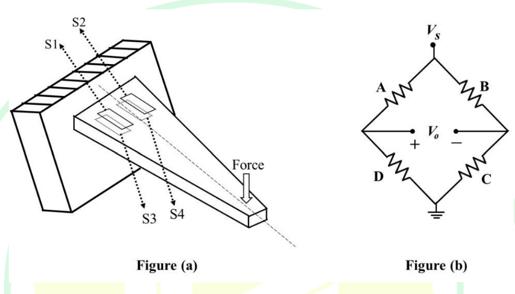
In the force transducer shown in Figure (a), four identical strain gauges S1, S2, S3, and S4 are mounted on a cantilever at equal distance from its base. S1 and S2 are mounted on the top surface and S3 and S4 are mounted on the bottom surface, as shown in the Figure (a). These strain gauges are to be connected to form a Wheatstone bridge consisting of four arms A, B, C, and D, as shown in the Figure (b). From the following options, the correct order to maximize the measurement sensitivity is
- AA S1, B S2, C S4, D S3
- BA S1, B S4, C S3, D S2
- CA S1, B S2, C S3, D S4
- DA S1, B S4, C S2, D S3
Solution & Step-by-step Explanation
To determine the correct connection of the strain gauges in a Wheatstone bridge to maximize measurement sensitivity, we need to understand how strain gauges work in different configurations.
Strain Gauge Working Principles:
- Strain gauges measure strain on a material. When the material deforms, the resistance of the strain gauge changes.
- In a Wheatstone bridge configuration, the change in resistance is used to produce a voltage output, which is indicative of the strain.
- Strain gauges on the top surface experience tension when the cantilever bends due to force, whereas those on the bottom experience compression.
Configuration Analysis:
- To maximize sensitivity, gauges experiencing opposite types of strain (tension and compression) should be placed in adjacent arms.
- This setup enhances the change in output voltage for a given force by increasing the relative change in resistance between the arms.
Correct Connection:
- A → S1 (Top, Tension)
- B → S4 (Bottom, Compression)
- C → S2 (Top, Tension)
- D → S3 (Bottom, Compression)
Thus, the correct order to maximize the measurement sensitivity is A → S1, B → S4, C → S2, D → S3.
Strain Gauge Working Principles:
- Strain gauges measure strain on a material. When the material deforms, the resistance of the strain gauge changes.
- In a Wheatstone bridge configuration, the change in resistance is used to produce a voltage output, which is indicative of the strain.
- Strain gauges on the top surface experience tension when the cantilever bends due to force, whereas those on the bottom experience compression.
Configuration Analysis:
- To maximize sensitivity, gauges experiencing opposite types of strain (tension and compression) should be placed in adjacent arms.
- This setup enhances the change in output voltage for a given force by increasing the relative change in resistance between the arms.
Correct Connection:
- A → S1 (Top, Tension)
- B → S4 (Bottom, Compression)
- C → S2 (Top, Tension)
- D → S3 (Bottom, Compression)
Thus, the correct order to maximize the measurement sensitivity is A → S1, B → S4, C → S2, D → S3.