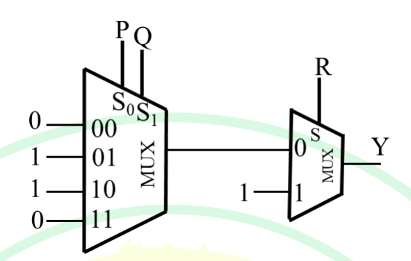
The minimized expression of the Boolean function Y(P, Q, R) implemented by the multiplexer (MUX) circuit shown in the figure is
- A
- B
- C
- D
Solution & Step-by-step Explanation
The given problem involves a multiplexer (MUX) circuit implementing a Boolean function Y(P, Q, R). We need to determine the minimized expression for this function.
Let's analyze the MUX circuit step-by-step:
1. The first MUX selects inputs based on the select lines P and Q (represented as S_1 and S_0 respectively).
2. The inputs to this MUX are 0, 1, 1, and 0, corresponding to 00, 01, 10, and 11 select line combinations.
3. This implements the function P \oplus Q (XOR gate), since: - When P = 0 and Q = 0 or P = 1 and Q = 1, the output is 0. - When P = 0 and Q = 1 or P = 1 and Q = 0, the output is 1.
4. The second MUX uses the output of the first MUX and select line R.
5. The second MUX outputs a logical function based on: - When R = 0, the output is the result from the first MUX, which is P \oplus Q. - When R = 1, the output is 1. - Effectively, the second MUX implements a logical OR operation: R + (P \oplus Q).
Thus, the minimized expression of the Boolean function is:
Y = R + (P \oplus Q)
Therefore, the correct answer is:
Y = R + (P \oplus Q)
Let's analyze the MUX circuit step-by-step:
1. The first MUX selects inputs based on the select lines P and Q (represented as S_1 and S_0 respectively).
2. The inputs to this MUX are 0, 1, 1, and 0, corresponding to 00, 01, 10, and 11 select line combinations.
3. This implements the function P \oplus Q (XOR gate), since: - When P = 0 and Q = 0 or P = 1 and Q = 1, the output is 0. - When P = 0 and Q = 1 or P = 1 and Q = 0, the output is 1.
4. The second MUX uses the output of the first MUX and select line R.
5. The second MUX outputs a logical function based on: - When R = 0, the output is the result from the first MUX, which is P \oplus Q. - When R = 1, the output is 1. - Effectively, the second MUX implements a logical OR operation: R + (P \oplus Q).
Thus, the minimized expression of the Boolean function is:
Y = R + (P \oplus Q)
Therefore, the correct answer is:
Y = R + (P \oplus Q)